Tel: +86-574-63783045 · ricky@idcpdu.com
| Incoming box current | 100–630 A (AC) / 400–800 A (DC) |
| Incoming box size | 850×430×223 / 1050×450×300 / 1100×450×300 mm |
| Incoming box function | Main MCCB, surge protection and metering to project requirement |
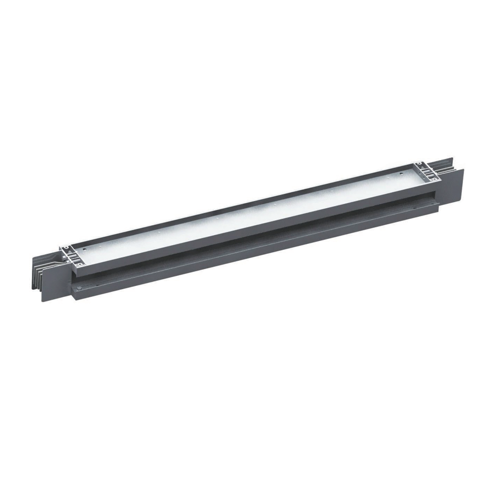
| Trunk current (AC) | 100–400 A at 180×156 mm / 630–800 A at 196×162 mm |
| Trunk current (DC) | 400–800 A at 180×156 mm |
| Trunk conductor | T2 copper bar, distributed heat-dissipation structure |
| Wiring system | 3-phase 5-wire (AC) |
| Standard trunk length | 1 m / 2 m / 2.4 m, custom length and elbow available |
| Trunk outlet | Socket or direct cable entry |
| Tap-off current | 16 A / 32 A / 63 A |
| Tap-off phase | Single-phase / three-phase |
| Tap-off outlet count | 1 / 2 / 3 |
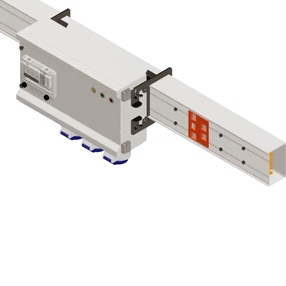
| Tap-off entry | Angled plug-in / straight plug-in / bottom cable exit |
| Tap-off option | Standard / metered / phase selection |
| Tap-off size | 230×260×150 to 400×260×150 mm |
| Configuration | Final configuration confirmed with sales and engineering |
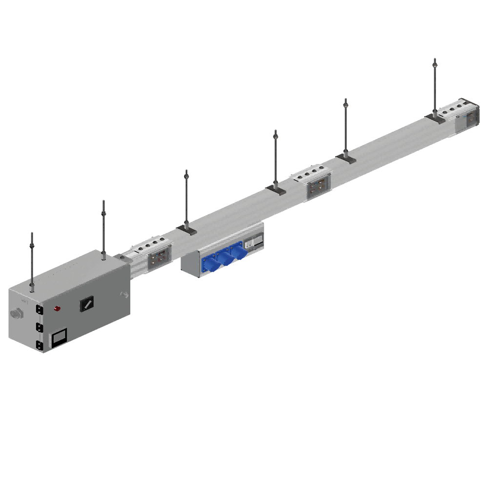
| System composition | Incoming box (feed unit) + dense busbar trunk (transmission) + plug-in tap-off units (distribution) |
| Replaces | Row-end distribution cabinet plus underfloor cable tray |
| Connection | Two-in-one tap-off and trunk design, pluggable under load |
| Cooling | Distributed heat-dissipation structure, air conduction through the housing |
| Customisation | Non-standard length, elbow and tap-off position per single-line diagram |
Datasheet, manual and drawings for this product (PDF).
Our engineers reply within 24 hours on business days.
Tel: +86-574-63783045
Email: ricky@idcpdu.com
Tell us your requirements — our sales team will get back to you with a quotation.
It replaces the row-end distribution cabinet, the underfloor cable tray and the field terminations behind them. A new row is then powered by plugging in a tap-off box instead of pulling another cable run.
16 A, 32 A or 63 A, single or three phase, with one to three outlets, in angled plug-in, straight plug-in or bottom cable exit versions — standard, metered, or with phase selection.
100–400 A runs use a 180×156 mm profile, 630–800 A a 196×162 mm profile, and DC 400–800 A the 180×156 mm profile. The profile follows the current class, so a low-current row stays compact.
T2 copper bars in a distributed heat-dissipation structure: heat leaves through the housing by air conduction instead of collecting at the joints, which keeps temperature rise low under continuous full load.
Main MCCB, surge protection and metering to project requirement, in 850×430×223, 1050×450×300 or 1100×450×300 mm; it covers 100–630 A AC or 400–800 A DC.
Yes. Straight sections are 1 m, 2 m and 2.4 m, and custom lengths and elbows are built to your single-line diagram; the final configuration is fixed together with our engineers before production.