Tel: +86-574-63783045 · ricky@idcpdu.com
| Rated current (Ie) | 400–6300 A |
| Rated insulation voltage (Ui) | 1000 V AC |
| Rated operating voltage (Ue) | 1000 V AC |
| Rated frequency | 50/60 Hz |
| Housing material | Aluminium-magnesium alloy |
| Housing colour | International grey (other colours on request) |
| Degree of protection | IP54 / IP66 |
| Conductor material | Copper / aluminium |
| Copper bars per phase | Per selected current class |
| Rated short-time withstand current (Icw) | Per selected current class |
| Rated peak withstand current (Ipk) | Per selected current class |
| Connector torque | 80 N·m ±5 N·m |
| Ambient temperature | -5 °C to +40 °C, 24 h mean 35 °C |
| Max. horizontal support spacing | 2 m |
| Installation category | IV |
| Pollution degree | 3 |
| Overall dimensions | Per selected current class |
| Weight | Per selected current class |
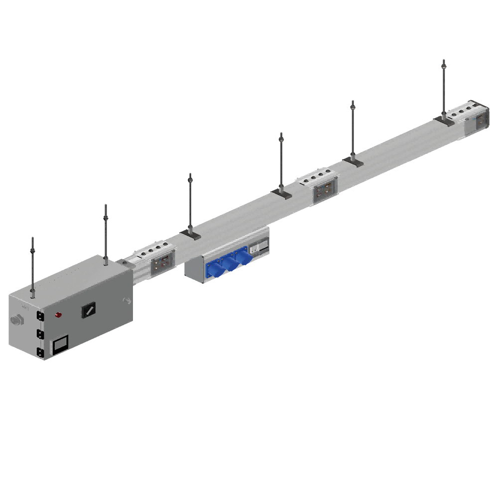
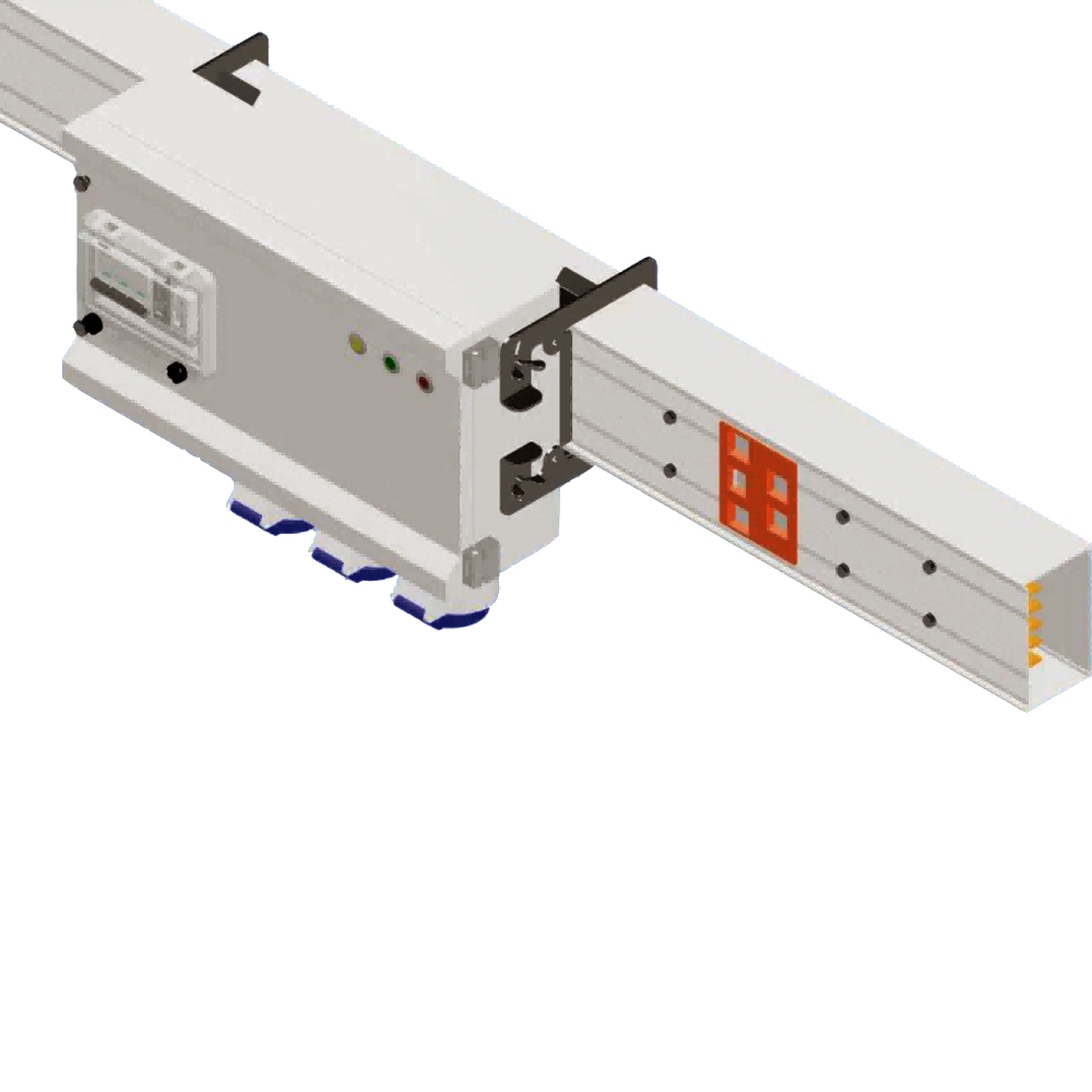
| System composition | Feed section from transformer or main switchboard + straight trunk sections + plug-in tap-off boxes |
| Replaces | Long cable busway runs and head-end distribution cabinets on main lines |
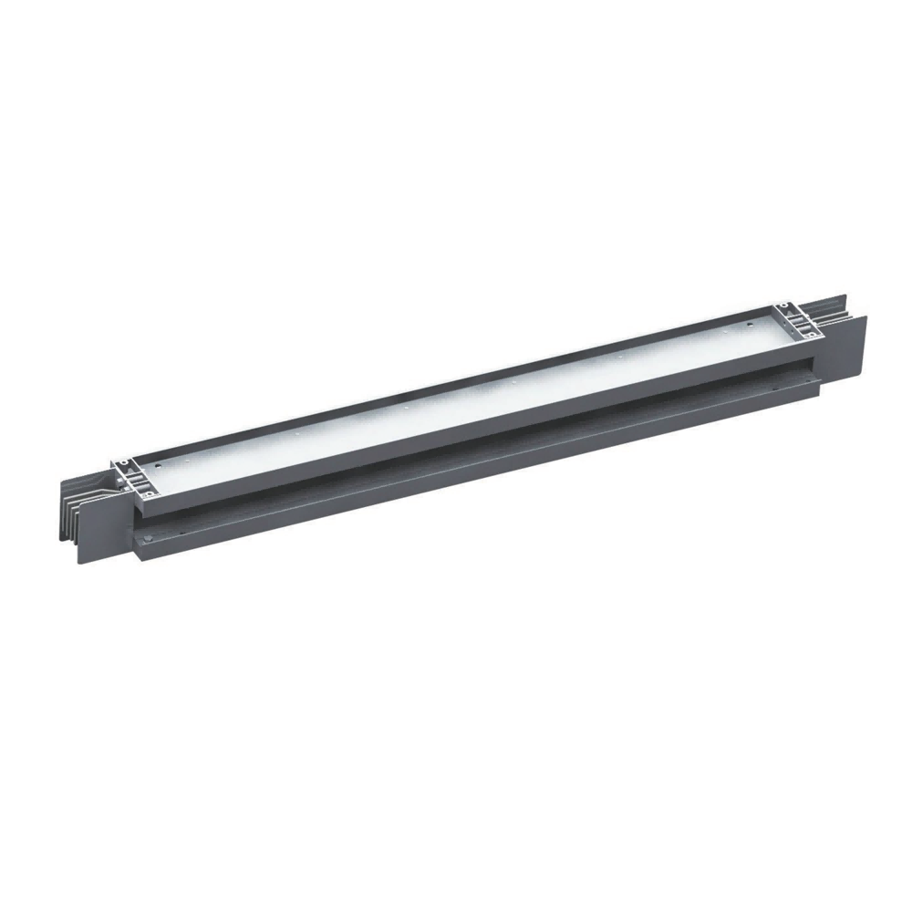
| Trunk lengths | 1 m / 2 m / 2.4 m standard, custom lengths and elbows available |
| Cooling | T2 copper bars in a distributed heat-dissipation structure, air conduction through the housing |
| Certification | Manufactured under ISO 9001; key components CE and EMC certified |
| Customisation | Route, support positions and tap-off points engineered to your single-line diagram |
Datasheet, manual and drawings for this product (PDF).
Our engineers reply within 24 hours on business days.
Tel: +86-574-63783045
Email: ricky@idcpdu.com
Tell us your requirements — our sales team will get back to you with a quotation.
Rated insulation voltage and rated operating voltage are both 1000 V AC, at 50/60 Hz.
Aluminium-magnesium alloy, closed to IP54 as standard and to IP66 where washdown or dust requires it; installation category IV with pollution degree 3.
T2 copper bars are standard, with aluminium available where weight matters. Bars per phase, overall dimensions and weight all follow the selected current class between 400 A and 6300 A.
Maximum horizontal support spacing is 2 m, and connector bolts are torqued to 80 N·m ±5 N·m, so joint resistance stays stable over the life of the run.
Both follow the current class selected. Give us the fault level from your single-line diagram and the run, its tap-offs and the protection settings are matched to it.
−5 °C to +40 °C with a 24-hour mean of 35 °C, which covers plant floors and substation rooms. Routes, supports and tap-off points are engineered from your single-line diagram — drawing in 30 minutes, quotation within the hour.