



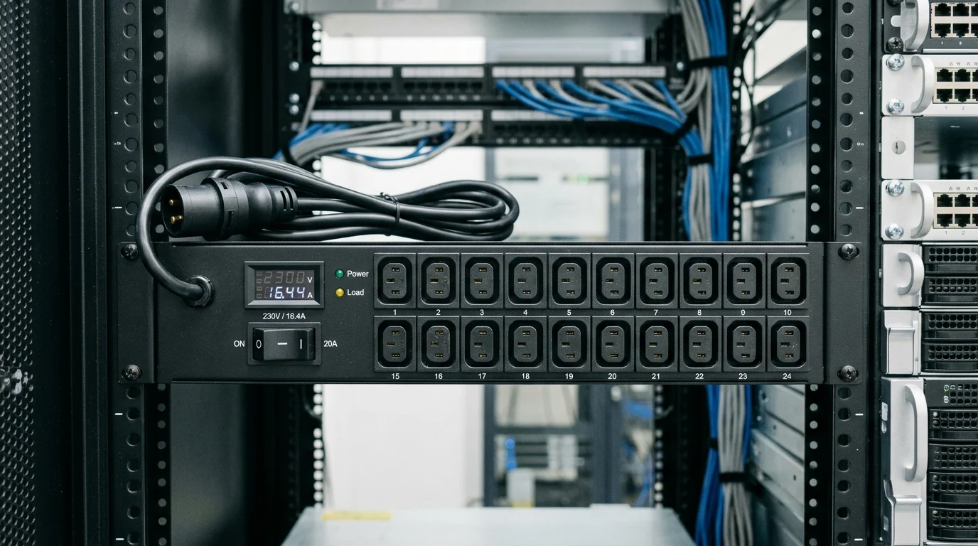
In large server rooms, cable organization is not just a housekeeping task—it directly affects uptime, cooling efficiency, and signal integrity. As racks move toward higher densities and PDUs deliver 208V or 415V three-phase power at significant amperage, careless routing can create electromagnetic interference, thermal stress, and obstructed airflow. The result may be higher bit error rates, degraded copper performance, or avoidable service interruptions in environments where every minute of downtime is costly. This guide explains how to organize network and PDU cabling with clear separation, proper vertical management, safe routing practices, and hardware choices that support reliable, scalable installations.
PDU Cable Management and Reliability
When we architect large-scale server installations, the physical layer dictates the long-term reliability of the facility. I consistently observe that improper integration of Power Distribution Unit (PDU) infrastructure with high-density network arrays leads to thermal and signal degradation. In enterprise environments where downtime averages $9,000 per minute, treating cable management as an afterthought is a severe liability.
Structured Cabling vs. Power Cabling
We must maintain a strict physical and logical distinction between structured data cabling and power delivery. Modern rack-mount PDUs often deliver three-phase power at 208V or 415V, drawing between 30A and 60A per whip. In contrast, our structured cabling—whether OM4 fiber optics or Cat6a copper—operates on delicate optical signals or low-voltage electrical pulses. Managing these distinct pathways requires deliberate routing strategies within the same 42U or 48U enclosure. We must ensure that the bulky, rigid power cords supplying the servers do not crush or obstruct the fragile data pathways. Often, we mount zero-U PDUs in the rear corners of the cabinet, keeping the heavy power whips entirely separated from the front-facing switch ports and patch panels.
Risks of Mixing Network and Power Cables
The primary risk of routing network and power cables together is Electromagnetic Interference (EMI). When unshielded twisted pair (UTP) cables run parallel to high-voltage PDU lines, the magnetic field generated by the alternating current induces noise on the data lines, causing elevated bit error rates. To mitigate this, our standard practice dictates a min. physical separation of 8 inches (200mm) between parallel UTP data cables and power conduits exceeding 2kVA. Additionally, high-amperage power cables generate significant heat. Bundling them tightly with data networks restricts airflow, potentially pushing copper cables beyond their max. operating temperature of 60°C (140°F). This thermal stress increases insertion loss and can permanently degrade the cable's internal jacket integrity.
PDU and Network Cable Organization Specs
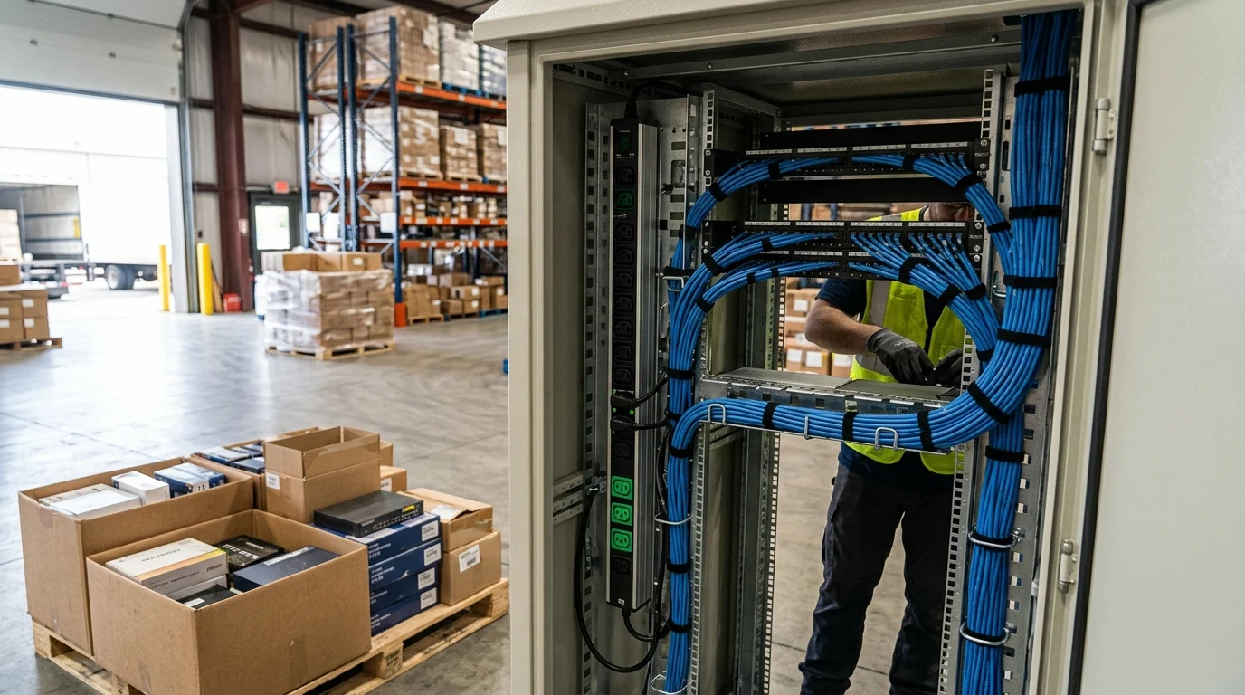
To enforce the physical separation required for reliable performance, we rely on precise hardware specifications and strict adherence to routing metrics. Selecting the correct organization hardware ensures that both our PDU power feeds and our high-density switch uplinks function without mechanical stress.
Vertical Cable Managers
Vertical cable managers are the backbone of our rack organization strategy. For high-density deployments, I recommend utilizing zero-U vertical managers that are at least 6 to 10 inches wide. We typically deploy dual-sided vertical managers, dedicating the front channel exclusively to network patch cords and the rear channel to PDU power cables and heavy trunk bundles. This front-to-back isolation physically prevents EMI while providing specialized mounting buttons for toolless PDU installation in the rear. By keeping the power distribution profile as slim as possible, we maximize the exhaust clearance for server fans, which is critical in racks drawing more than 10kW of power.
Bend Radius and Fill Ratio
Adhering to strict bend radius and fill ratio limits is non-negotiable for our installations. According to ANSI/TIA-568 standards, the min. bend radius for a Cat6a cable is four times its outside diameter, translating to roughly 1.18 inches (30mm). Exceeding this radius alters the cable's internal geometry, causing near-end crosstalk (NEXT) and signal reflections. Furthermore, we never exceed a 50% fill ratio in any vertical or horizontal manager. A 40% initial fill ratio is our strict operational target. This leaves exactly 10% of the manager's cross-sectional area available for future Moves, Adds, and Changes (MACs) while ensuring adequate ambient airflow to cool adjacent PDU components.
| Specification Category | Metric / Threshold | Primary Rationale |
|---|---|---|
| Data/Power Separation | Min. 8 inches (200mm) | Prevents EMI from high-voltage PDU lines |
| Vertical Manager Width | 6 to 10 inches | Accommodates high-density Cat6a and fiber bundles |
| Cat6a Min. Bend Radius | 4x Outer Diameter (~1.18 in) | Prevents NEXT and physical signal degradation |
| Cable Manager Fill Ratio | 40% initial (50% max.) | Ensures airflow and scalability for future MACs |
Practical Cable Organization Process
Establishing a rigorous, repeatable process for cable deployment is the final step in securing our physical infrastructure. A standardized workflow allows our technicians to deploy hundreds of racks with identical precision, in turn reducing future troubleshooting time by up to 60%.
Plan, Route, Bundle, Label, and Test
Our methodology follows a strict, sequential operating procedure: plan, route, bundle, label, and test. We map out the PDU placement and switch port assignments in our Data Center Infrastructure Management (DCIM) software before a single cable is pulled. During routing and bundling, we exclusively use hook-and-loop fasteners spaced every 12 to 18 inches along the run. Plastic zip ties are strictly prohibited in our data centers, as overtightening them easily crushes the cable jacket and permanently alters the internal impedance. For labeling, we adhere to the ANSI/TIA-606-B standard, applying machine-printed, wrap-around labels at both ends of every power and data connection. Finally, every data drop is certified using a calibrated Fluke tester to verify compliance with baseline insertion loss and return loss metrics.
Upfront Cost vs. Long-Term Maintainability
I often encounter pushback regarding the initial capital expenditure required for premium cable management and intelligent PDUs. High-capacity vertical managers, overhead raceways, and color-coded cabling can increase the initial per-rack hardware cost by 15% to 20%, sometimes adding $500 to $800 per enclosure. However, this upfront investment is rapidly offset by the reduction in operational expenditures. When a server inevitably fails, the ability to trace a labeled power cord to a specific PDU receptacle and a data cable to its exact switch port within seconds drastically minimizes our Mean Time to Recovery (MTTR). In my experience managing enterprise deployments, properly organized racks extend the lifecycle of the cabling infrastructure by at least 5 to 7 years. This proves that disciplined organization is not just an aesthetic preference, but a core component of long-term facility economics.
Key Takeaways
- Keep structured data cabling and PDU power cabling on separate physical pathways to reduce EMI, heat transfer, and mechanical damage.
- Maintain at least 8 inches, or 200mm, of clearance between parallel UTP cables and power conduits exceeding 2kVA.
- Mount zero-U PDUs in rear rack corners to keep heavy power whips away from switch ports, patch panels, and front-side data cabling.
- Use 6- to 10-inch zero-U vertical cable managers in dense racks to provide enough space for organized, low-stress routing.
- Separate front network channels from rear power channels in dual-sided managers to improve airflow and simplify maintenance.
- Avoid tight bundles of high-amperage power and data cables because excess heat can push copper cabling toward its 60°C limit.
Frequently Asked Questions
Why should PDU power cables be separated from network cables?
Separating PDU power cables from network cables reduces EMI, prevents heat buildup, and protects fragile fiber or copper pathways from mechanical stress caused by heavier power cords.
What separation distance is recommended between UTP data cables and high-power lines?
For parallel runs near power conduits above 2kVA, maintain at least 8 inches, or 200mm, of physical separation to reduce induced noise and bit errors.
Where should zero-U PDUs be mounted in high-density racks?
Zero-U PDUs are commonly mounted in the rear corners of 42U or 48U cabinets, keeping power whips away from front-facing switch ports and patch panels.
How do vertical cable managers improve PDU and network cable organization?
Vertical cable managers create dedicated routing channels, often separating front network patch cords from rear PDU power cables, improving airflow, access, and reliability.
What width is recommended for vertical cable managers in dense installations?
For high-density deployments, zero-U vertical cable managers should typically be 6 to 10 inches wide to handle cable volume without excessive compression.