



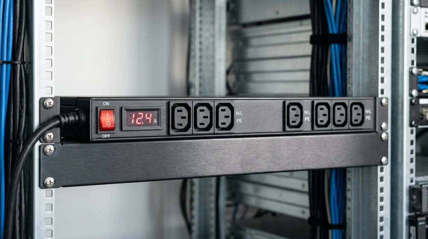
Rack power decisions made on day one can determine whether a data center scales smoothly or becomes expensive to retrofit later. Servers may turn over every three to five years, but the PDU layer often stays in place for seven to ten, making early choices about capacity, redundancy, and monitoring especially important. This article explains how to build a rack power foundation that supports higher-density workloads, 2N resilience, and operational visibility from the start. By comparing PDU types, 3-phase power options, and safe utilization targets, teams can avoid stranded capacity, reduce downtime risk, and prepare their infrastructure for growth.
Why define a PDU strategy before the first rack
When architecting data center environments, the power distribution unit (PDU) is often relegated to an afterthought, overshadowed by the procurement of high-performance servers and core switches. However, defining a comprehensive PDU strategy before racking the first server is critical to long-term success. Compute hardware typically operates on a three-to-five-year refresh cycle, but core rack power infrastructure is expected to last seven to ten years. Retrofitting power distribution into an active, live production environment introduces unacceptable downtime risks and significantly inflated labor costs.
What scalable rack infrastructure requires
A truly scalable rack infrastructure requires a standardized power foundation that anticipates future hardware generations rather than just solving today's immediate needs. Designing for maximum flexibility at the cabinet level is essential. If infrastructure is deployed to support only a standard 5kW load today, scaling to high-density 15kW or 20kW racks for AI, machine learning, or dense virtualization workloads tomorrow will require complete power chain replacements. Standardizing on 3-phase power delivery—such as 208V (the North American standard) or 415V (common in Europe and Asia)—drastically reduces the volume of copper cabling required under the raised floor or in overhead cable trays. This approach not only lowers initial material costs but also improves phase balancing across the entire data hall, maximizing the efficiency of upstream transformers.
How to plan for power density, redundancy, and growth
Planning for power density requires aligning PDU capabilities with thermal limitations and redundancy expectations. A common best practice is implementing a 2N redundancy model, utilizing distinct A and B power feeds originating from completely separate uninterruptible power supply (UPS) systems. To accommodate future growth without violating failover capacity, facility designs often ensure that under normal operating conditions, neither the A nor B PDU exceeds 40% of its maximum rated capacity. If a primary feed fails, the surviving PDU instantly absorbs the load, spiking to 80% utilization. This keeps the load safely within standard continuous load limits, such as those defined by the National Electrical Code (NEC), while helping to preserve high-availability targets like 99.999% uptime. While optimal thresholds vary by facility design and regulatory jurisdiction, ignoring these general capacity limits can lead to cascaded breaker trips during a utility failure.
Which PDU specifications should you compare

Selecting the right hardware requires a careful evaluation of operational requirements against available technology. Moving beyond simple outlet counts, it is important to analyze the telemetry, environmental resilience, and remote control capabilities that will support long-term automation and efficiency goals.
How to compare basic, metered, monitored, and switched PDUs
The market offers four distinct tiers of rack power distribution, each serving specific operational maturity levels. Moving from basic power strips to intelligent infrastructure requires justifying the capital expenditure against operational savings. The following matrix can guide procurement decisions based on remote management needs and density, though specific cost multipliers will vary by vendor, region, and deployment scale.
| PDU Tier | Telemetry Level | Remote Switching | Relative Cost Premium | Ideal Use Case |
|---|---|---|---|---|
| Basic | None | No | Baseline (1.0x) | Unmanaged edge nodes |
| Metered | Local LED display only | No | 1.2x - 1.5x | Small server rooms |
| Monitored | Network-grade (SNMP/API) | No | 2.0x - 2.5x | High-density enterprise racks |
| Switched | Outlet-level network data | Yes | 3.0x - 4.0x | Lights-out data centers |
For most scalable environments, industry standards recommend at least monitored PDUs. The ability to integrate outlet-level power consumption data into Data Center Infrastructure Management (DCIM) platforms is invaluable for identifying stranded power capacity and optimizing workload placement.
Which electrical, mechanical, and environmental factors matter
Beyond digital intelligence, evaluating the electrical and mechanical tolerances of the units is essential. From a mechanical perspective, vertical 0U models save valuable rack space, but their physical dimensions must not obstruct hot-swappable server fan trays or dense fiber cabling pathways. Environmentally, standard 45°C (113°F) models are suitable for many traditional environments. However, as facilities push for higher cooling efficiency through hot-aisle containment, the ambient temperature at the rear of the rack increases significantly. In these elevated return-temperature scenarios, specifying PDUs rated for continuous operation at 60°C (140°F) is justified to prevent premature control board failures under extreme thermal loads. Furthermore, standardizing on locking C13 and C19 receptacles prevents accidental disconnects during routine maintenance, and utilizing hydraulic-magnetic circuit breakers ensures stable trip curves regardless of the ambient rack temperature.
How do you implement a scalable PDU deployment plan
With the strategy defined and specifications selected, the final phase is executing a deployment plan that minimizes stranded capacity while allowing for rapid, frictionless scaling. This requires tight alignment between IT operations and facility engineering teams.
What steps to follow for capacity planning
Effective capacity planning relies on baselining and predictive modeling rather than guesswork. A common starting point is calculating the nameplate power draw of the initial hardware stack and applying a derating factor—typically around 60% to 70% of the manufacturer's maximum nameplate rating—to estimate the actual peak operating draw. However, a frequent deployment pitfall is an over-reliance on nameplate derating without conducting actual measured load profiling. Other common mistakes include neglecting inrush current coordination with breaker trip curves or failing to validate SNMP/DCIM integration during procurement.
To maintain NEC compliance and ensure safe failover, industry practice generally caps the maximum continuous load at 80% on all branch circuits. For example, on a standard 30-amp circuit, the designed continuous load is capped at 24 amps. By monitoring live power consumption trends through DCIM tools, operators can accurately forecast when a specific rack will breach this threshold. This data-driven approach allows facilities to proactively provision additional power drops weeks before a capacity bottleneck impacts compute deployments.
How to balance cost control and scalability
Balancing cost control with the need for scalability is a continuous operational challenge.
Key Takeaways
- Plan the PDU architecture before deploying the first rack because power infrastructure typically remains in service for seven to ten years.
- Design for future 15kW to 20kW high-density racks instead of limiting the power chain to today’s 5kW requirements.
- Use 3-phase power where appropriate to reduce copper cabling, improve phase balancing, and support higher cabinet-level power density.
- In a 2N redundancy model, keep each A and B PDU near or below 40% utilization during normal operation to preserve failover capacity.
- Compare PDU tiers by telemetry, remote switching, environmental monitoring, and automation value rather than outlet count alone.
Frequently Asked Questions
Why should a PDU strategy be defined before installing the first rack?
A PDU strategy should come first because rack power infrastructure often lasts seven to ten years, longer than server refresh cycles. Planning early reduces retrofit costs, avoids downtime, and ensures the rack can support future high-density workloads.
What rack power capacity should I plan for from day one?
Do not design only for today’s 5kW rack loads. If future AI, virtualization, or dense compute workloads may reach 15kW to 20kW per rack, select PDUs and upstream power paths that can scale without full replacement.
Why is 3-phase power recommended for scalable rack infrastructure?
3-phase power, such as 208V in North America or 415V in Europe and Asia, can reduce copper cabling, improve phase balancing, and support higher rack densities more efficiently than many single-phase designs.
How should A and B PDUs be loaded in a 2N design?
A common approach is to keep each PDU below about 40% load during normal operation. If one feed fails, the surviving PDU can carry the full load at roughly 80%, staying within safer continuous load limits.
What is the difference between metered, monitored, and switched PDUs?
Metered PDUs provide local power readings, monitored PDUs add remote telemetry, and switched PDUs allow remote outlet control. The right choice depends on density, uptime goals, and how much remote management the site requires.